(continued)
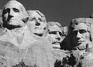
Image Enhancements by Kevin Klettke and Eric C. Lausch
© 2001 Danger Zone! Productions
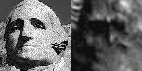
Image Enhancements by Kevin Klettke and Eric C. Lausch Below, we offer an additional image for comparison. Superimposed on the craggy shelf which overhangs the tube entrance are the four biggest guys in rock. Although woefully out of scale (the Rushmore faces are approximately 60 feet high), it helps define perspective on these huge carvings as the viewer becomes removed in distance from them. (I simply could not resist doing this!) This author sees a striking similarity between this image from Mars and what sculptor Gutzon Borglum intended to create when he began drilling into the 5,725-foot mountain in 1927. Perhaps we should start calling them the four biggest Earth guys in rock!
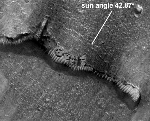
Image Enhancements by Kevin Klettke and Eric C. Lausch
Colorization
Colorization is simply a method of highlighting details in an image with
some color in order to make them more discernible. Sort of like separating the wheat from the chaff.
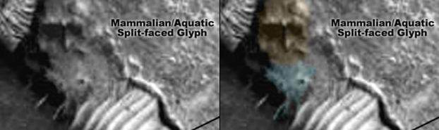
Image Enhancements by Kevin Klettke and Eric C. Lausch
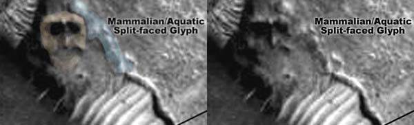
Image Enhancements by Kevin Klettke and Eric C. Lausch
Photoclinometry (Shape from Shading Analysis)
where R is the reflectance map, p = dz/dx and q = dz/dy are the partial
derivatives of the surface in the x- and y-directions, and a is a constant
that depends on the albedo, the gain of the imaging system and other
factors. The above expression also assumes that any additive offsets, e.g.,
due to atmospheric scattering, have been removed. However, We would be remiss not to elucidate on the limitations of photoclinometry: In an e-mail to Chris Joseph, who had inquired about photoclinometry and MOLA, Lori Fenton, a grad student at CalTech describes the shortcomings of photoclinomtery.
The worst problem with photoclinometry is that you can never tell by looking at an image, particularly on Mars where you can't go there and find out what you're really imaging, whether the shading effects are due to topography or change in albedo. Anything from compositional to textural changes can cause a change in albedo, and most photoclinometry programs assume that the albedo is constant across the image. Unfortunately there's no good way to figure out what the true pattern of albedo really is, and so you're stuck assuming that it is constant, but you have to keep this in mind when you solve for topography.Dr. Carlotto has commented in the past that the change in albedo on the tubes has made them a poor candidate for SFS due to the very reasons that Ms. Fenton discusses in her photoclinometry papers. However, the roof of this edifice appears to be of a uniform albedo, not alternating area of bright and dark as we've observed in other images of these anomalies where the bright "ribs" alternate with the darker tube walls. The Martian Mega Split Faced Glyph also is fairly consistent in albedo. (If carved or constructed it stands to reason the material composition at least on the exterior would be uniform and have a fairly uniform albedo). The main changes are at the eye sockets, the left side of the head and the mouth of the fish due to the lighting angle and subsequent shadowing. It's my official opinion as a lay person that this image is a pretty good candidate for photoclinometry! (Input is welcome from you experts out there!) Our first two SFS offerings were processed using the Mars 3D Launcher. (It also does MOLA datasets IF they are available.....)
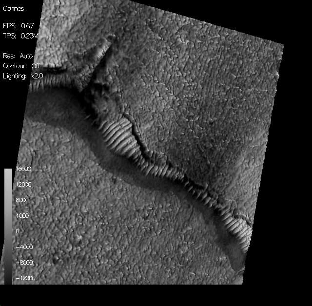
Image Enhancements by Eric C. Lausch
In my estimation, these images are visually compelling evidence that this
highly anomalous object on the planet Mars is no mere sand dune as
postulated by JPL. This appears, at least to me, to be an intelligently designed edifice. And a strikingly beautiful one at that. Whether sculpted from native Martian rock or produced by some organic technology unbeknownst to our ilk, it fills me with wonder and curiosity.
Perhaps this is the kind of awe ancient sojourners felt when gazing upon the
Colossus of Rhodes or the Hanging Gardens of Babylon for the first time.
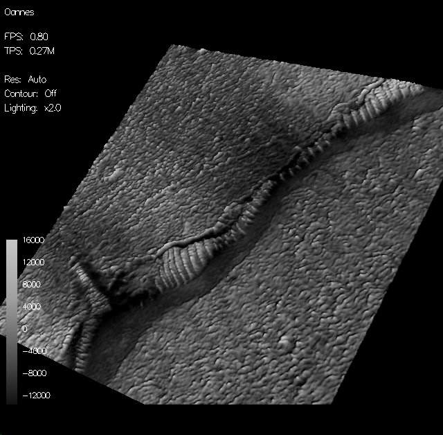
Image Enhancements by Eric C. Lausch The really amazing thing in this image is the tunnels themselves. Just to the left of the humanoid sculpture one can plainly see the curvature of the tube running in a generally north-south direction away from this terminal under the surface of Mars. Moving from left to right there appears to a series of these tubes parallel to the first all leaving this main nexus in a perpendicular alignment. These are not readily discernible in the 2 dimensional image.
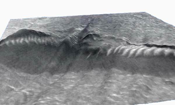
Shape from Shading analysis and texture mapping By Chris Joseph
MOLA DATA Interpretation 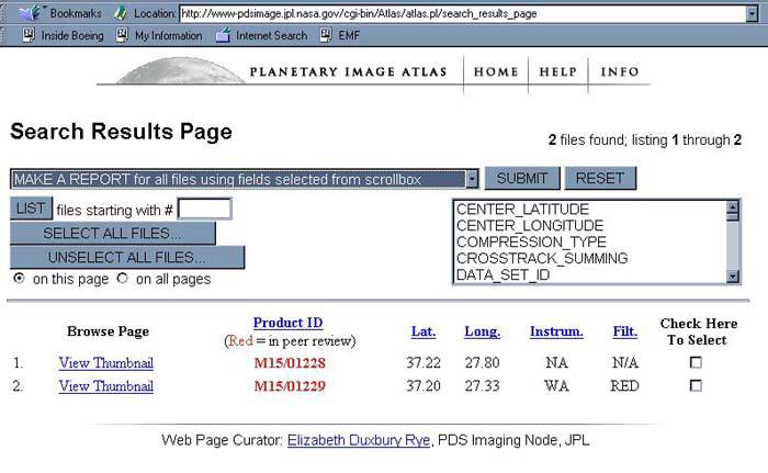 Planetary Image Atlas web page denoting MOLA Data in peer review (as shown in red lettering). We were quite disappointed at the lack of availability of the pertinent MOLA data as it is required for comparison to the photoclinometry analysis. We will process and post the results of this data when it becomes available. An e-mail note to web curator for the archive requesting an ECD for peer review completion has at the time of this writing produced no response. How ironic that the very data needed to corroborate the photoclinometry results is being not made available to the American taxpayer who funds these projects. Apparently there is documentation that shows this is not the first time that NASA\JPL\MSSS have played less than scrupulous games with MOLA data. Mr. Danger is of the opinion that his posting of this image is the cause for the data not being available. The image and MOLA data were obtained in May, 2000. While this does seem like an inordinately long period for peer review I'd chalk it up to the inefficiency of the Jet Propulsion Laboratory to accomplish their tasks in a timely manner. The recent debacles of the past few years at JPL even spawned a series of articles on Space.com which portray JPL as a poorly managed leaking ship adrift in an ocean of organizational chaos. While I doubt a conspiracy is being promulgated I would like to get a timely response and clear answer as to when this data will become available to the American public whose daily toil finances ventures such as this.
The way these work is the left picture is on the right, and right on left...
they are actually "taken" about 5 degrees off from each other, and provide
the parallax (view) you need to see 3 dimensions. Relax your focus and let
your eyes cross until it looks like there are three images. The one in the
center should be 3D, like Tom Corbett on ViewMaster. It is essentially the same process used to make 3D images with those red and blue glasses that came with 3D comic books when we were kids, except that it uses no color (thus requiring no 3D glasses). (I actually physically cross my eyes to view these. It works quite well and they haven't gotten stuck that way-yet!)
The following was created by making a Bryce2/3D/4 scene into true 3D Stereo color image. Images that will appear to float inches in front of (or
behind) your monitor screen! In fact the basic technique can be applied to
any images that consist of separate left and right eye views; be they
photographs, drawings or computer generated imagery. These are real 3D
stereo images (anaglyphs). When the two images are then merged into a single image, the left eye will see only the right image and the right eye the left image. Because of the offset between the left/right images the brain
interprets the 'depth' giving the viewer the impression of a true 3D image.
A tutorial on the process can be found here.
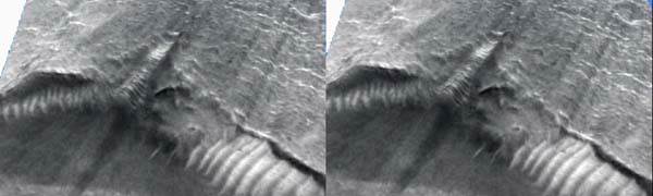
Stereo Pairing By Chris Joseph © 2001 Christopher Joseph and Danger Zone! Productions
Reflections on liquid water
Quoting a recent article from Spaceflight Now:
Baker points to several lines of evidence in support of his claim. For
example, MGS images of the planet's northern plains and southern highlands
shows regions relatively free of craters, implying they were altered in the
recent past. These regions also have a polygonal terrain that is similar to
what is seen in permafrost regions on Earth.
Baker thinks that Mars may go through cycles of extended cold, dry periods
punctuated by warmer, wetter spells. While the cold periods can last
hundreds of millions of years, the warmer periods may last just a few tens
of thousands of years. Moreover, Baker believes that there may be cold
interludes within those brief warmer periods, and that Mars today may be in
such a brief cold period.
"We don't know the answer to that yet -- that's very speculative," he said.
"But if it's true, it would have major implications for sending people to
Mars, because it may mean that water is more available than otherwise
thought."
The warm periods are triggered, Baker believes, by a period of massive
volcanic activity. The heat from that activity melts ice trapped below the
surface, possibly enough to form a temporary ocean in the planet's northern
region. A greenhouse effect created by carbon dioxide released into the
atmosphere through the volcanic activity warms the atmosphere and allows
water to remain in liquid form at the surface."
Perhaps, not volcanic activity, but another mechanism causes these warm
periods. Presently the entire planet Mars is engulfed in a planetary wide dust storm which has increased global temperatures by over 30 degrees Celsius (86 degrees Fahrenheit)! The Martian southern polar cap has been shrinking steadily during the mapping phase of the MGS mission.
This same TES (Thermal Emission Spectrometer) data shows that from 45 degrees S and 60 degrees S latitude "Zonally averaged daytime bolometer brightness temperatures" of 23 degrees C at 45 degrees S! That's right! A balmy 73 degrees Fahrenheit!
(Might as well be Miami in January!)
In layman's terms, "Warm enough for liquid water to be found on the surface of Mars!" (Shucks folks - that's warm enough to take a dip!)
A tantalizing speculation is that when the dust from this Mega-storm settles
an open sea might be found at the location of the former northern polar cap!
It's probably not likely but it's an interesting notion.....
If Baker is right Mars could be entering into one of it's warm phases at
this very moment.
Other data shows us that the temperature on mars is downright balmy at the
surface but cools rapidly just a few feet above it. Thus it is plausible that we could be seeing liquid water in this image from the low-lying northern plains of Mars.
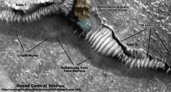
Image Enhancements by Kevin Klettke and Eric C. Lausch As we know this image was taken at 1300 Mars time, early afternoon with an incidence angle of 42.87 degrees as noted in the MGS Data table, illuminating these edifices from the upper right of the images it is conceivable that the lighter area directly in front of the "tunnel" entrance is indeed light being reflected off the "roof" if the tunnel enclosure onto a large pool of liquid water on the surface of Mars. And as I'm sure we all remember from high school physics class, "the angle of incidence equals the angle of reflection". Since we know the position of the sun is to the upper right this basic property of optical theory would seem to support the contention that these are indeed reflections from the lightly colored surface of the "tunnel" enclosures roof. But once again we must re-iterate that lacking precise topographical survey information the best we can hope to do is extrapolate from the available data. |